INTRODUCTION
I was always interested in solar power, but for twenty-eight years we lived in a swamp surrounded by sun-blocking trees. Here in Prince Edward County we are completely exposed to wind and sunshine. The sight of all that energy going unused while we paid for propane bothered me. The plan was to start with a pair of test panels beside the house to preheat water going to the water heater. That would later be expanded to more panels in the back field to help heat the house in the winter. The test panels were completed in 2016. The house-heating panels will never be built. The reason? Not enough sunlight in the winter to make it practical. Clear winter days are rare in this area.
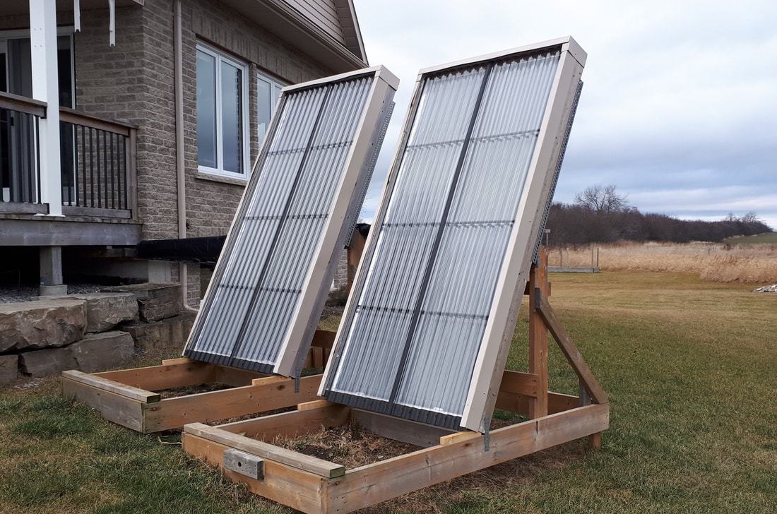
The two test panels that pre-heat water going to our hot water heater were located beside the house for convenience. The never-built panels for heating the house would have been located in the back field away from the shadow of the house, but that presented a problem. The simplest system for cold climates is a drain-back system. When the pump turns off (no Sun) the water in the panel drains down into the storage tank and the panel is safe from freezing. To drain completely, the surface of the water in the storage tank must be lower than the bottom of the panels. The options for installing panels in the back field were to raise the panels (not happening in this wind-whipped area) or bury the storage tank (not practical because we are just above bedrock). What I needed was a way to have the panels at ground level with the large storage tank at the same level. That resulted in the Reservoir in Panel approach. The two hot-water heating panels were built to test that approach.
THE RESERVOIR-IN-PANEL SYSTEM
The Reservoir in Panel System
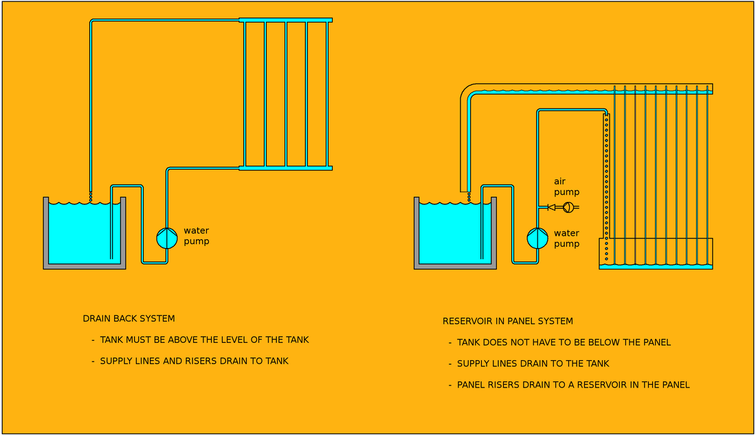
The left side of the diagram above shows a drain-back system. When the pump turns off, the water in the panel drains back into the storage tank which is located in a heated building. The exposed panel is then safe from damage if the temperature drops below freezing.
The right side of the diagram shows the reservoir-in-panel system. When the pump turns off, the water in the supply line drains back to the tank as before. The return line also drains back, but in this case a large ABS plastic pipe is used to ensure that as water drains to the tank, air can travel in the reverse direction to allow the water in the risers to drop into the reservoir. The other difference is that the supply line goes to the top of the panel. The water then drops to the reservoir through a large, copper pipe. The large pipe ensures that, when the pump turns off, the water in that pipe travels one way (dropping down to the reservoir) while the air in the pipe travels up, allowing the supply line water to drain back to the tank and the water in the risers to drop to the reservoir.
A small air pump (aquarium bubbler) injects air into the supply line to ensure that the reservoir always holds a layer of air above the water to give the water room to expand when it freezes. The panels have been frozen several times without harm. In normal operation the air pump stores some air in a tank to help purge the panels at the end of the day.
THE FINISHED SYSTEM
|
|
|
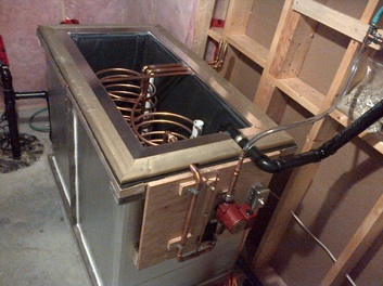
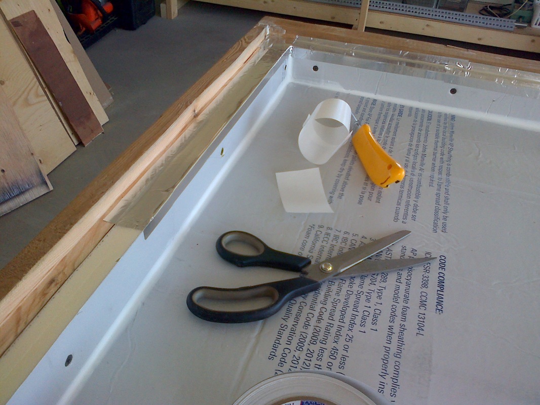
The tank being finished. It holds 440 litres of water.
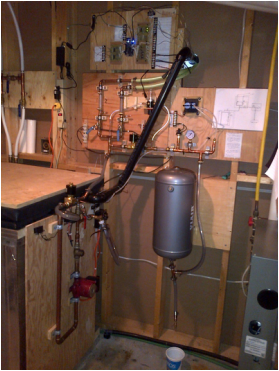
The control system. It doesn't need to be this complicated. A lot of this was for troubleshooting.
|
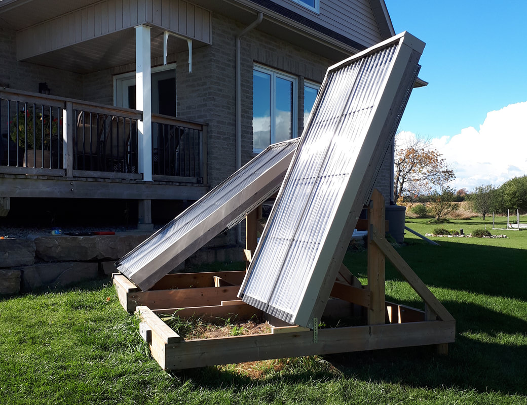
The panels in place
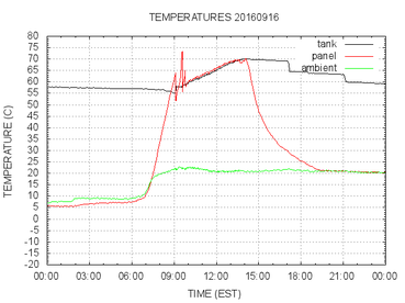
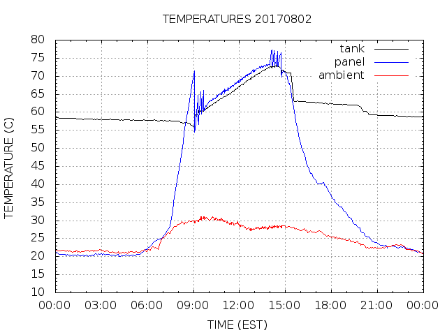
A clear day in September. The water pump doesn't turn on until the panel temperature reaches 40C above the ambient temperature. It turns off when the returning water drops below the temperature of the tank. The two steps at 17:00 and 21:00 show the result of removing 30 litres of water from a hot water faucet.
|
PANEL CONSTRUCTION DETAILS
|
|
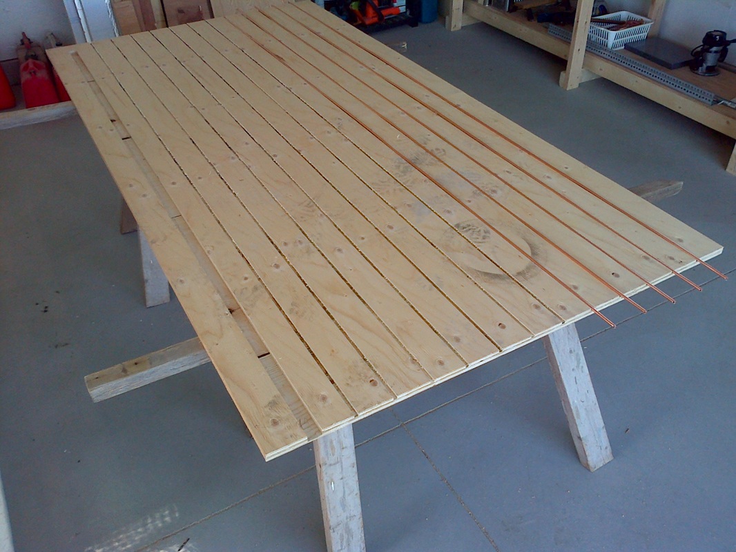
From top left to bottom right:
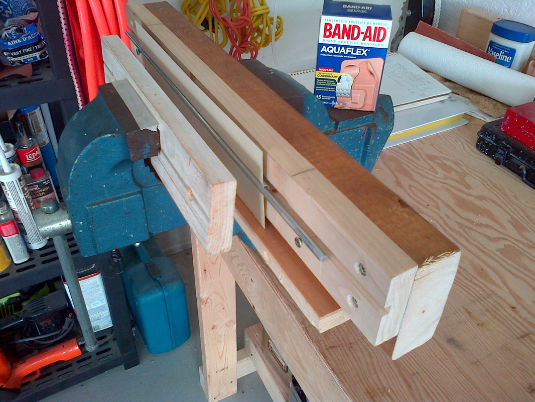
-the tube support. 3/4" (19mm) plywood with grooves routed to accept the down tube and risers.
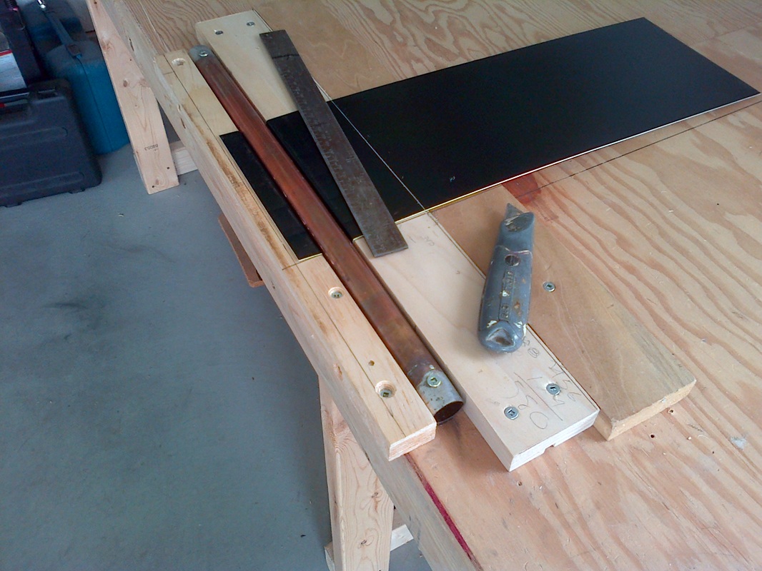
-shaping the first layer of aluminum for the risers (the vise thread showed signs of distress when finished).
-shaping the first layer of aluminum for the down tube. Ignore the colour change. I ran out of beige.
-the first aluminum layer stapled into place.
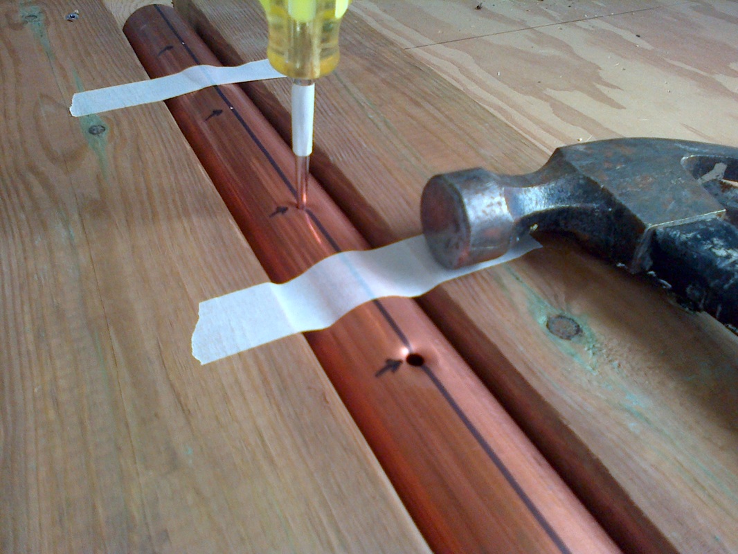
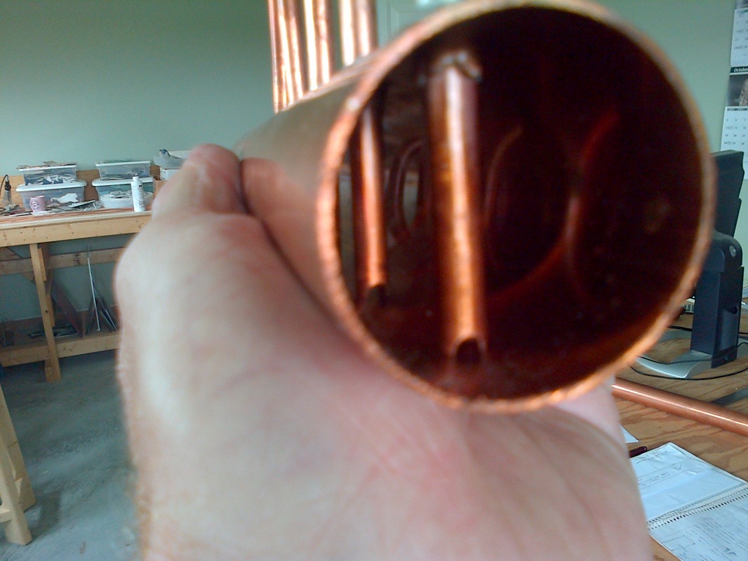
-perforating the reservoir tube to accept the risers.
-the perforations give a large surface area for soldering the risers. The joint is strong.
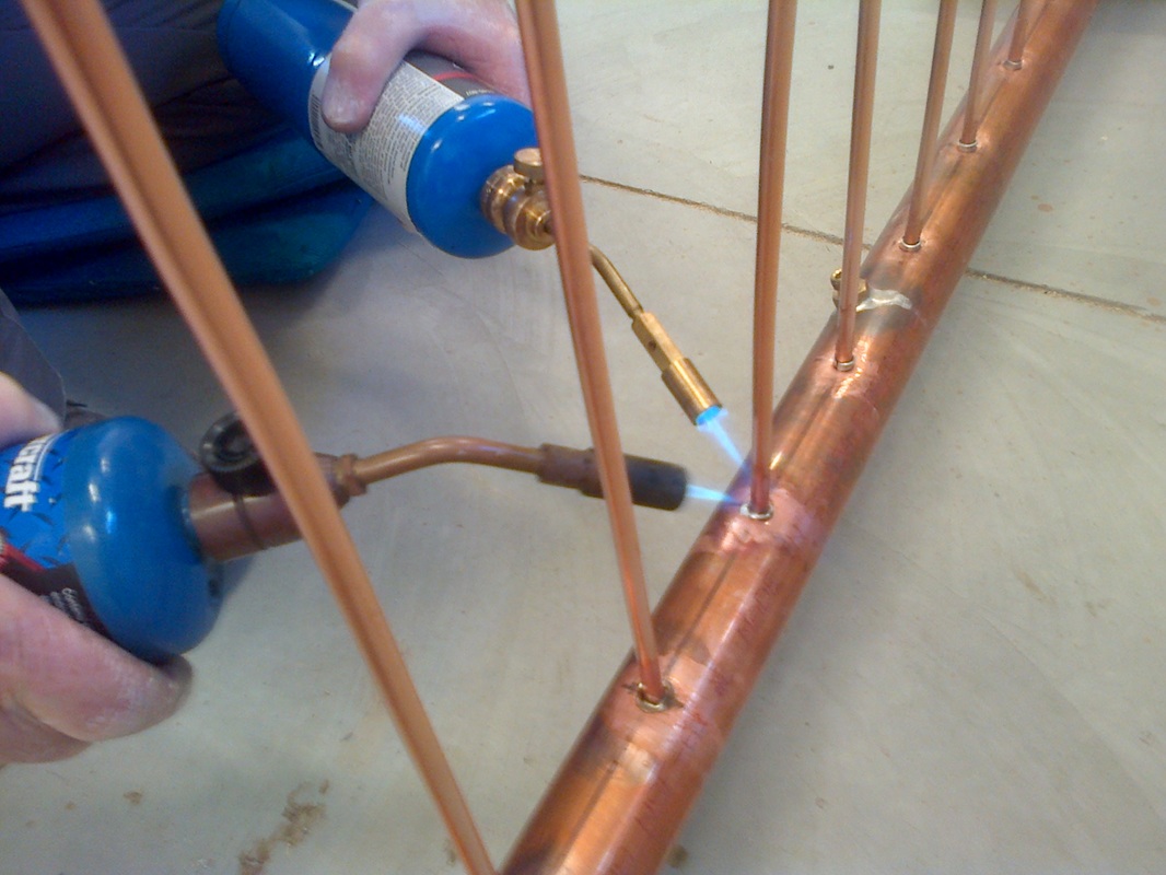
-soldering. Preforms were made by flattening and rolling solder.
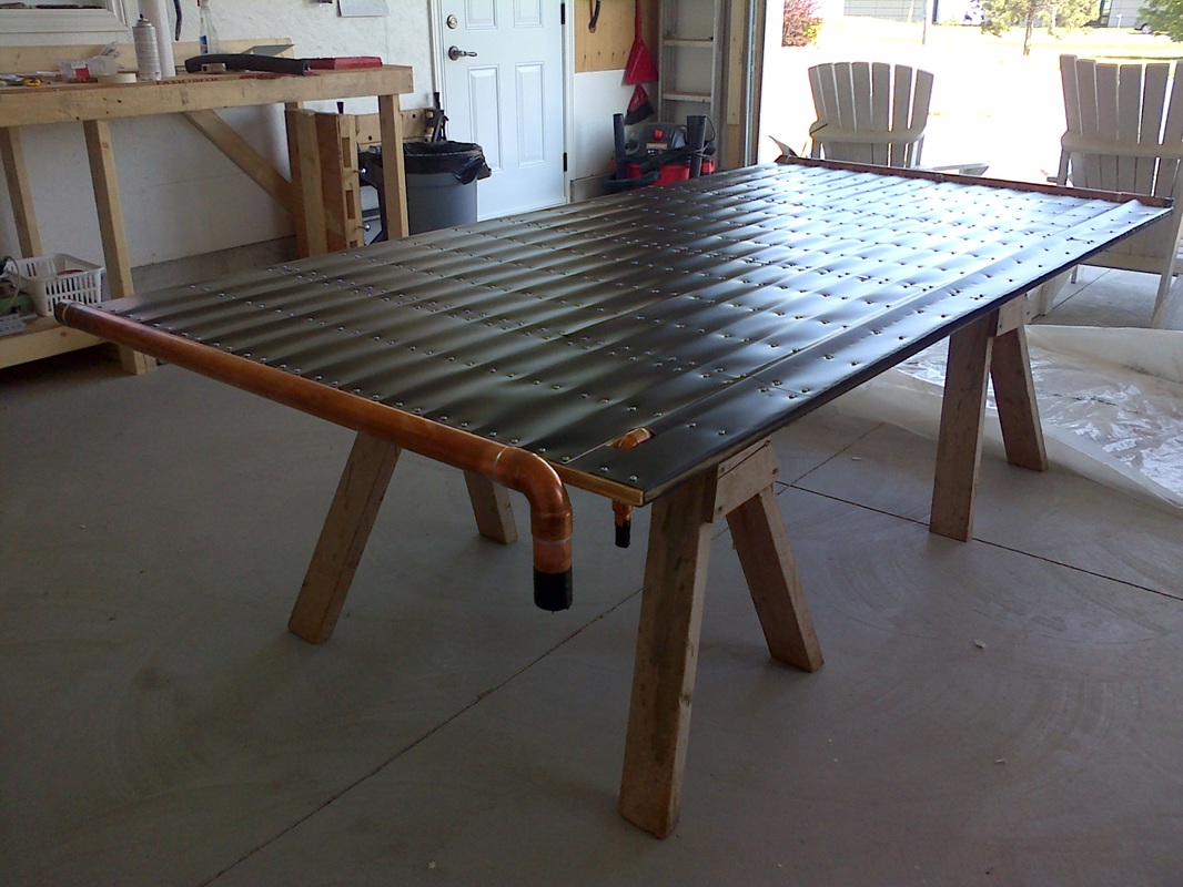
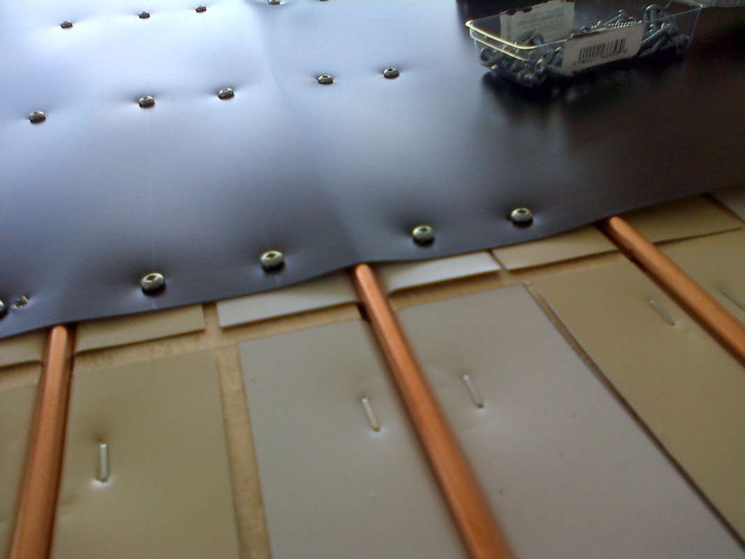
-screwing the second layer of aluminum into place. The aluminum comes in 24" (61 cm) widths.
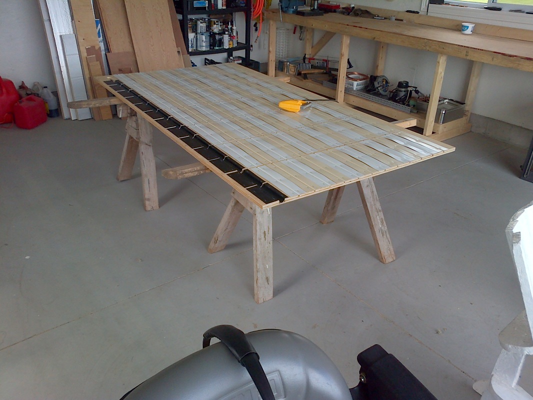
-the finished inner panel.
-insulating the box with polyisocyanurate insulation. 50mm on the back. 25mm on the sides.
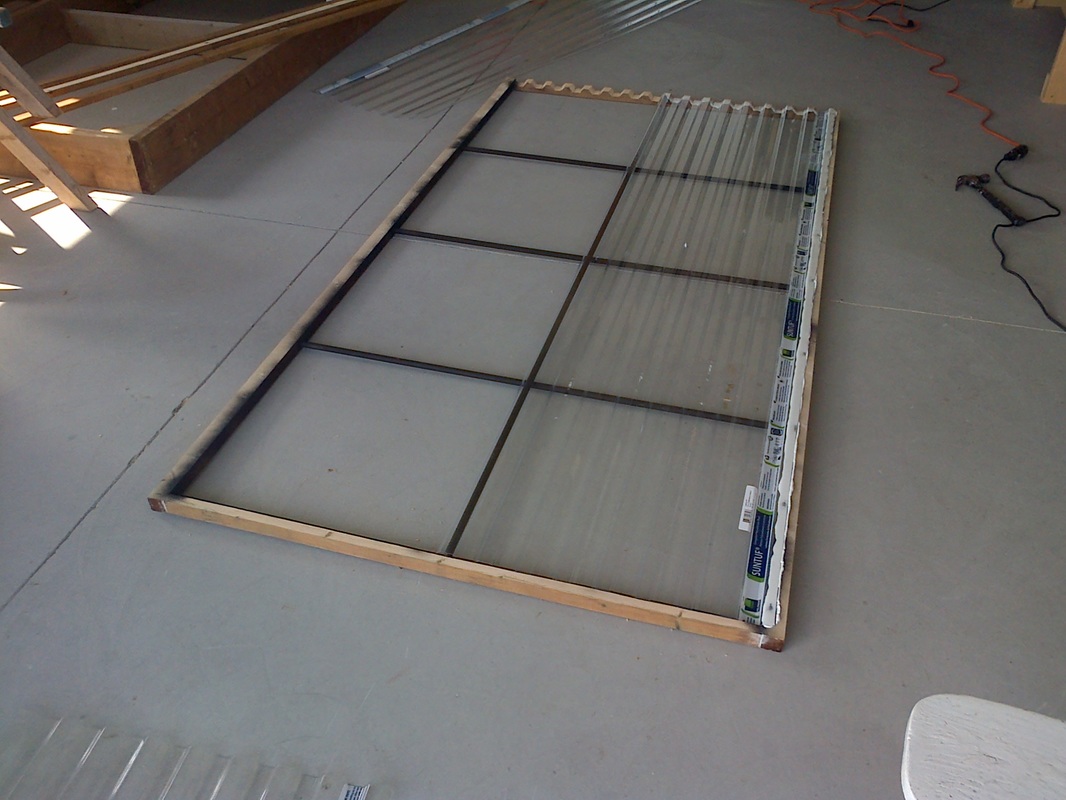
-the outer polycarbonate window being installed into its frame. The inner window has no outer frame.
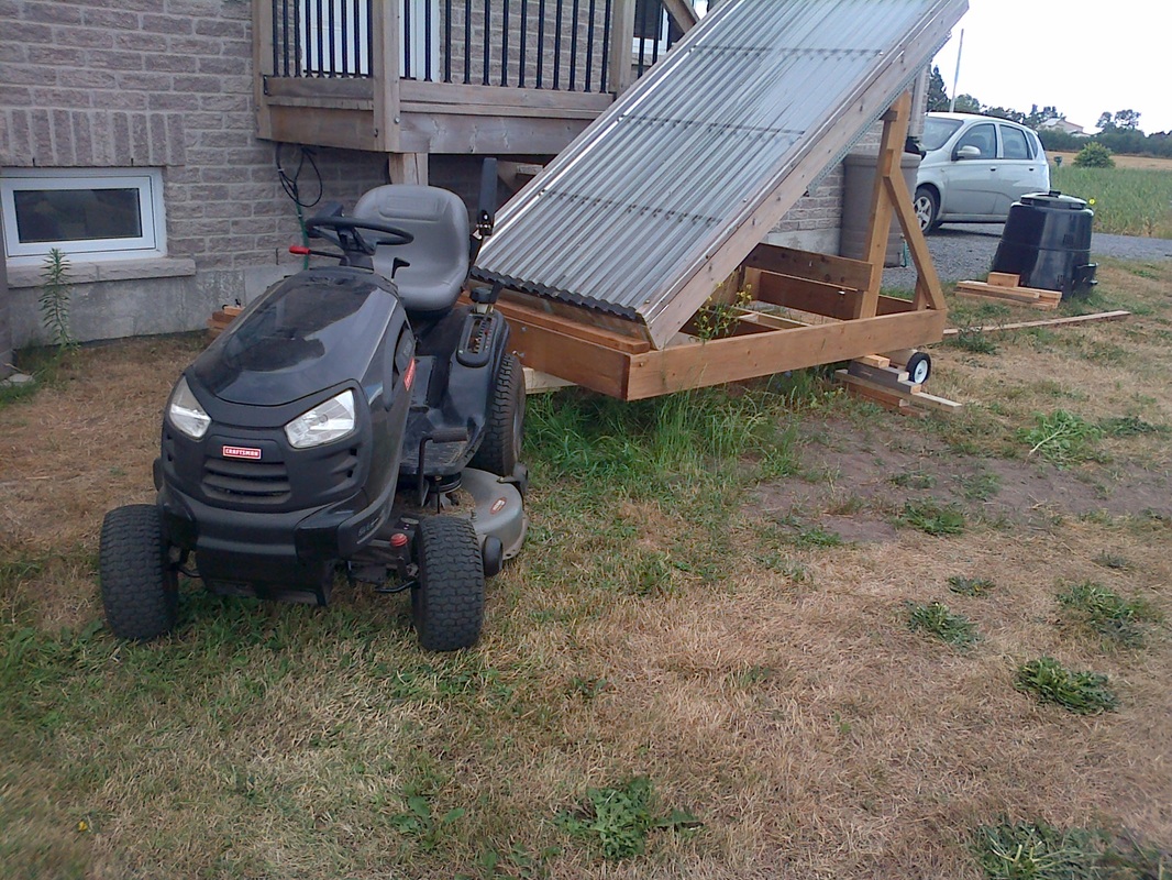
-the panel on its cradle. The cradle is on a trailer for transport.
-the tube support. 3/4" (19mm) plywood with grooves routed to accept the down tube and risers.
-shaping the first layer of aluminum for the risers (the vise thread showed signs of distress when finished).
-shaping the first layer of aluminum for the down tube. Ignore the colour change. I ran out of beige.
-the first aluminum layer stapled into place.
-perforating the reservoir tube to accept the risers.
-the perforations give a large surface area for soldering the risers. The joint is strong.
-soldering. Preforms were made by flattening and rolling solder.
-screwing the second layer of aluminum into place. The aluminum comes in 24" (61 cm) widths.
-the finished inner panel.
-insulating the box with polyisocyanurate insulation. 50mm on the back. 25mm on the sides.
-the outer polycarbonate window being installed into its frame. The inner window has no outer frame.
-the panel on its cradle. The cradle is on a trailer for transport.
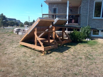
Shown above: changing the panels from the summer to winter inclinations. Extender pipes are added to the supply and return lines to adjust for the different run lengths.
SOME RESULTS:
SOME RESULTS:
|
|
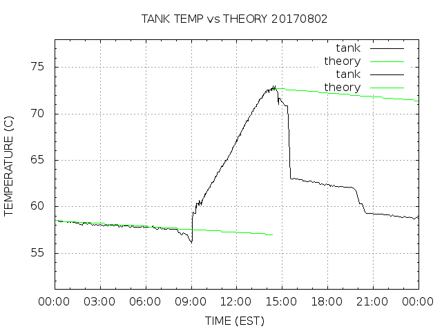
One glorious, sunny day in August 2017. The left graph shows the actual tank, panel and ambient temperatures in Celsius. The right graph shows the tank temperature again (black) with two theoretical temperatures in green. The left green line shows the theoretical temperature drop due to heat loss through the tank walls from midnight to 14:00. It follows the actual temperature until 09:00, because no hot water was used overnight. The right green line starts at the maximum tank temperature and shows what the temperature would have been if no hot water had been used. In this case, between 14:00 and the end of the day the actual temperature dropped by 12.7 C due to hot water use.
The tank holds an average of 410 kg of water. A one degree temperature drop of 410 kg of water requires 1.7 MJ of heat, so a 12.7 degree drop means that 21.6 MJ was used to pre-heat the supply water that day. 1 litre of propane produces 24.8 MJ (17 MJ of useful heat assuming that our water heater is 68% efficient). So that day the system saved 1.3 litres of propane. At the present price that's about 80 cents, and that's on a very good day.
The tank holds an average of 410 kg of water. A one degree temperature drop of 410 kg of water requires 1.7 MJ of heat, so a 12.7 degree drop means that 21.6 MJ was used to pre-heat the supply water that day. 1 litre of propane produces 24.8 MJ (17 MJ of useful heat assuming that our water heater is 68% efficient). So that day the system saved 1.3 litres of propane. At the present price that's about 80 cents, and that's on a very good day.
|
|
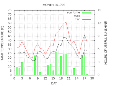
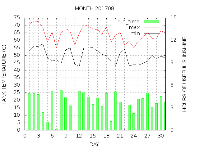
The two graphs show the difference between winter and summer in this area. October to April are cloudy months. These graphs are from February and August of 2017. The red and black lines show the max and min tank temperatures for each day. The green bars show how many hours of operating time were available on a given day. Lots of hot water in the summer.
THE BOTTOM LINE
Was it worth it? Not financially. The amount of propane saved over the last four years:
2017: 232 litres
2018: 222 litres
2019: 263 litres
2020 240 litres
The cost of propane is WAY less than $1 / litre (US or Canadian).
The cost of building the system (tank, panels and control system):
copper and aluminum: $ 1278
plywood, iso insulation, lumber: $ 1757
control system uP, valves: $ 858
I also show $ 2035 listed under "general", which sounds ridiculous although I was a good customer of the local hardware store throughout. This year (2020) I replaced the polycarbonate plastic windows on the panels. Each 2 ft (60cm) panel cost $50, and there a four of them per panel.
Of course when propane hits $10 / litre I'll be laughing.
